This section is divided into a number of subsections, links to which are:
Remove[ "Global`*"] // Quiet (* remove all variables *)
2D Rotations
A 2D rotation about the origin has only one parameter, the angle, which defines the amount of rotation. The standard convention found in most math books is to consider counterclockwise rotation positive and clockwise rotation negative. We can do rotation about the origin using matrix multiplication. A rotation matrix is a transformation matrix that is used to perform a rotation of a plane by angle θ in counterclockwise direction.We begin with rotating a point P(x₀, y₀) in the xy-plane about the origin through an angle θ in counterclockwise direction. We demonstrate derivation of the rotation matrix in two ways. First, we use trigonometric relations, and then show that the same matrix can be obtained based on rotations of basic vectors i = (1, 0) and j = (0, 1),
Suppose that a given point P(x₀, y₀) is moved under rotation by angle θ into a new point Q(x, y). In order to derive the rotation matrix, we recognize that the new point Q will be the same distance from the origin as the starting point P. So both points P and Q lie on the circle centered at the origin and radius r. The point Q is just an extra angle θ, as measured from the positive abscissa (= x-axis) relative to the position of P at this circle. If the point P is at angle ϕ, then the new point Q is at the angle ϕ + θ. Since all the points on the circle of radius r with center at the origin can be written as \( \displaystyle r\,e^{{\bf j}\alpha} = \left( r\,\cos\alpha , r\,\sin\alpha \right) \) for some real number α. We know that point P has coordinates \( \displaystyle r\,e^{{\bf j}\phi} = \left( r\,\cos\phi , r\,\sin\phi \right) , \) while point Q has coordinates \( \displaystyle r\,e^{{\bf j}(\phi + \theta )} = \left( r\,\cos (\phi + \theta ) , r\,\sin (\phi + \theta ) \right) , \) where j is the unit vector in the positive vertical direction on complex plane ℂ so j² = −1.

|
circle = Graphics[{Blue, Thickness[0.01], Circle[{0, 0}, 3]}];
p = {3 Cos[Pi/6], 3 Sin[Pi/6]};
q = {3 Cos[Pi/6 + 3*Pi/5], 3 Sin[Pi/6 + 3*Pi/5]};
arc = Graphics[{Red, Thickness[0.015],
Circle[{0, 0}, 3, {Pi/6, Pi/6 + 3*Pi/5}]}];
angles = Graphics[{Black, Thick,
Circle[{0, 0}, 1.7, {Pi/6, Pi/6 + 3*Pi/5}],
Circle[{0, 0}, 0.9, {0, Pi/6}]}];
points = Graphics[{PointSize[0.05], Purple, Point[{p, q}]}];
lines = Graphics[{Black,
Thickness[0.01], { Arrow[{{0, 0}, p}], Arrow[{{0, 0}, q}]}}];
txt = Graphics[ {Black,
Text[Style["P", FontSize -> 18, Bold], {2.9, 1.9}],
Text[Style["Q", FontSize -> 18, Bold], {-2.5, 2.3}],
Text[Style["\[Theta]", FontSize -> 18, Bold], {-0.01, 0.5}],
Text[Style["\[Phi]", FontSize -> 18, Bold], {1.1, 0.25}]}];
ll = Graphics[{Black, Thick, Arrow[{{0, 0}, {3.5, 0}}]} ];
txt2 = Graphics[ {Black,
Text[Style["O", FontSize -> 18, Italic], {0, -0.4}],
Text[Style["x", FontSize -> 18, Italic], {3.3, 0.3}]}];
Show[circle, arc, angles, points, lines, txt, ll, txt2]
|

In order to determine the rotation matrix, we express coordinates of point Q through coordinates of point P. To accomplish this task, we use trigonometric identities and delegate this job to Mathematica:
We can derive the rotation matrix \eqref{EqPlane.2} by considering transformation of base vectors i = (0, 1) and j = (0, 1).
p = {1, 0};
q = {0, 1};
\[Theta] = 60 Degree
pPr = {Cos[\[Theta]], Sin[\[Theta]]};
qPr = {-Sin[\[Theta]], Cos[\[Theta]]} ;
Graphics[{Black, , Thick, Arrow[{{0, 0}, p}], Arrow[{{0, 0}, q}], Blue, Thick, Arrow[{{0, 0}, pPr}], Arrow[{{0, 0}, qPr}], Red, Thick, Arrow[Circle[{0, 0}, .25, {0, 60 Degree}]], Arrow[Circle[{0, 0}, .25, {Pi/2, 150 Degree}]], Text["i={1,0}", {.9, .05}], Text["j={0,1}", {-.11, .9}], Text["p={Cos(\[Theta]), Sin(\[Theta])}", pPr + .05], Text["q={-Sin(\[Theta]), Cos(\[Theta])}", qPr + .05], Text["\[Theta] = 60\[Degree]", {.35, .15}], Text["\[Theta] = 60\[Degree]", {-.15, .28}]}, Axes -> True, PlotLabel -> "Rotation in counterclockwise direction"]

p = {1, 0};
q = {0, 1};
\[Theta] = 60 Degree;
pPr = {Cos[\[Theta]], Sin[\[Theta]]};
qPr = {-Sin[\[Theta]], Cos[\[Theta]]};
Graphics[{Black, Thick, Arrow[{{0, 0}, p}] , Arrow[{{0, 0}, q}] , Blue, Thick, Arrow[{{0, 0}, pPr}] , Arrow[{{0, 0}, qPr}] , Red, Thick, Arrow[Circle[{0, 0}, .25, {0, 60 Degree}]] , Arrow[Circle[{0, 0}, .25, {Pi/2, 150 Degree}]] , Text["i={1,0}", {.9, .05}] , Text["j={0,1}", {-.11, .9}] , Text["p={Cos(\[Theta]), Sin(\[Theta])}", pPr + .05] , Text["q={-Sin(\[Theta]), Cos(\[Theta])}", qPr + .05] , Text["\[Theta] = 60°", {.35, .15}] , Text["\[Theta] = 60°", {-.15, .28}]} , Axes -> True , PlotLabel -> "Rotation in counterclockwise direction"]


|
\[ \frac{1}{2} \begin{bmatrix} \sqrt{3} & -1 \\ 1 & \sqrt{3} \end{bmatrix} \] |

|

|
\[ \frac{1}{2} \begin{bmatrix} -\sqrt{3} & -1 \\ 1 & -\sqrt{3} \end{bmatrix} \] |

|

|
\[ \frac{1}{2} \begin{bmatrix} 0 & -1 \\ 1 & \phantom{-}0 \end{bmatrix} \] |

|

|
\[ \frac{1}{2} \begin{bmatrix} \phantom{-}0 & 1 \\ -1 & 0 \end{bmatrix} \] |

|
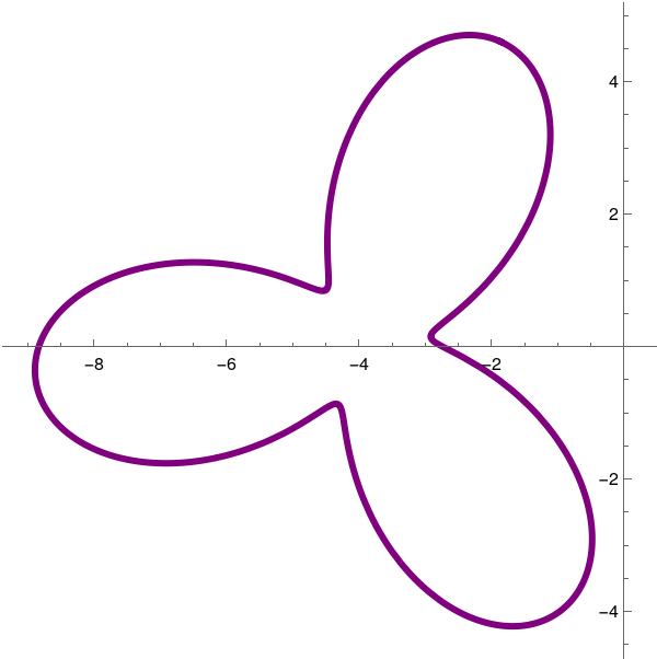
F = (2*Cos[3*t] + 3)*Cos[t];
G = (2*Cos[3*t] + 3)*Sin[t];
origPlot = ParametricPlot[{F, G}, {t, 0, 2*Pi}, PlotStyle -> {Blue, Thickness[0.01]}]
centerPlot = ListPlot[{Flatten[center]}, PlotMarkers -> {"+", Medium}];
sho2 = Show[rotPlot, centerPlot, PlotRange -> All]

|

|
An alternative method
G = (2*Cos[3*t] + 3)*Sin[t];
origPlot = ParametricPlot[{F, G}, {t, 0, 2*Pi}, PlotStyle -> {Blue, Thickness[0.01]}];
P = {F, G}; center = {-2, -3}; Q = R . (P - center) + center; (* We don't need to flatten Q here *)
The latter figure clearly depicts the rotation of the parametric curve. Now let us animate the rotation so all intermediate curves will be visible.
G = (2*Cos[3*t] + 2)*1*Sin[t];
origPlot = ParametricPlot[{F, G}, {t, 0, 2*Pi}, PlotStyle -> {Blue, Thickness[0.01]}];
P = {{F}, {G}};
R = {{Cos[a], -Sin[a]}, {Sin[a], Cos[a]}};
center = {{-2}, {-3}};
QP = R.(P - center) + center;
centerPlot2 = Graphics[{Red, PointSize -> Medium, Point[{-2, -3}]}];
rotPlot = ParametricPlot[Flatten[Q], {t, 0, 2*Pi}, PlotStyle -> {Purple, Thickness[0.01]}]; anim2 = Animate[QPE = Evaluate[QP /. {a -> theta}]; QPEPlot = ParametricPlot[Flatten[QPE], {t, 0, 2*Pi}, PlotStyle -> {Black, Thickness[0.01]}]; Show[origPlot, QPEPlot, rotPlot, centerPlot2, PlotRange -> {{-10, 10}, {-10, 10}}], {{theta, 0, a}, 0, 2*Pi, Pi/16}, AnimationRepetitions -> Infinity ]

- Consider the point P(2,1). Without using matrix multiplication, find the resulting point undr rotation about the origin by angles π/2 and π/4.
- Given a point P on the plane ℝ², let Q be the point corresponding to the rotation of P in counterclockwise direction about the origin through an angle θ. Let R be the point corresponding to the rotation of Q in counterclockwise direction about the origin through an angle ϕ. Verify that \[ \mathbf{R}[\phi ]\,\mathbf{R}[\theta ] = \mathbf{R}[\phi + \theta ] , \] where R[θ] is the rotation matrix according to formula (1). Does it mean that products of rotation matrices are commutative?
- Find the coordinates of the point Q corresponding to the point P(3, 2) that has been rotated in counterclockwise direction about the origin through an angle θ = 2π/3.
- Anton, Howard (2005), Elementary Linear Algebra (Applications Version) (9th ed.), Wiley International
- Dunn, F. and Parberry, I. (2002). 3D math primer for graphics and game development. Plano, Tex.: Wordware Pub.
- Foley, James D.; van Dam, Andries; Feiner, Steven K.; Hughes, John F. (1991), Computer Graphics: Principles and Practice (2nd ed.), Reading: Addison-Wesley, ISBN 0-201-12110-7
- Matrices and Linear Transformations
- Rogers, D.F., Adams, J. A., Mathematical Elements for Computer Graphics, McGraw-Hill Science/Engineering/Math, 1989.
- Watt, A., 3D Computer Graphics, Addison-Wesley; 3rd edition, 1999.

