Gallery of Circuits
We start with simple one loop circuits:
connect[pointList_] := {Line[pointList],
Map[Text[Style["", FontSize -> 18]] &, pointList[[{1, -1}]]]}
▢
This code outlines the "connect" function. It connects a line between a list
of points. ▢ Syntax: connect[{{x1, y1}, {x2, y2}, ...{xn, yn}}]
gap[l_: 1] := Line[l {{{0, 0}, {1/3, 0}}, {{2/3, 0}, {1, 0}}}]
▢
This function is used to create the gap in the battery function.
resistor[l_: 1, n_: 3] :=
Line[Table[{i l/(4 n), 1/3 Sin[i Pi/2]}, {i, 0, 4 n}]
▢
This code outlines the "resistor" function. It draws a zig-zag line across a
sinusoidal function to represent a resistor within the electrical circuit. ▢ Syntax: resistor[]//at[{x, y}, Θ]
coil[l_: 1, n_: 3] :=
Module[{scale = l/(5/16 n + 1/2),
pts = {{0, 0}, {0, 1}, {1/2, 1}, {1/2,
0}, {1/2, -1}, {5/16, -1}, {5/16, 0}}},
Append[Table[
BezierCurve[scale Map[{d 5/16, 0} + # &, pts]], {d, 0, n - 1}],
BezierCurve[scale Map[{5/16 n, 0} + # &, pts[[1 ;; 4]]]]]]
▢
This code outlines the coil function. It draws a looping line using
BezierCurve, which is a curve approximation through the given set of points.
▢ Syntax: coil[]//at[{x, y}, Θ]
capacitor[l_: 1] := {gap[l],
Line[l {{{1/3, -2/3}, {1/3, 2/3}}, {{2/3, -2/3}, {2/3, 2/3}}}]}
▢
This code outlines the "capacitor" function. It uses the previous gap function
and lines to draw a simple capacitor.▢ Syntax: capacitor[]//at[{x, y}, Θ]
battery[l_: 1] := {gap[
l], {Rectangle[l {1/3, -(2/3)}, l {1/3 + 1/9, 2/3}],
Line[l {{2/3, -1}, {2/3, 1}}]}}
▢
This code outlines the battery function which is used to draw a battery
at the given point and direction. It is used in conjunction with the at
function. ▢ Syntax: battery[]//at[{x, y}, \[CapitalTheta]]
contact[l_: 1] := {gap[l],
Map[{EdgeForm[Directive[Thick, Black]], FaceForm[White],
Disk[#, l/30]} &, l {{1/3, 0}, {2/3, 0}}]}
Options[display] = {Frame -> True, FrameTicks -> None, PlotRange -> All, GridLines -> Automatic, GridLinesStyle -> Directive[Orange, Dashed], AspectRatio -> Automatic};
▢
This code sets up the options for the plotting grid. It can be adjusted for
style purposes (the grid lines can be removed, for example. They are useful
for plotting).
Options[display] = {Frame -> True, FrameTicks -> None, PlotRange -> All, GridLines -> Automatic, GridLinesStyle -> Directive[Orange, Dashed], AspectRatio -> Automatic};
at[position_, angle_: 0][obj_] :=
GeometricTransformation[obj,
Composition[TranslationTransform[position],
RotationTransform[angle]]]
▢
This code outlines the at function. It is used to set the position and
orientation of the batteries, resistors, and capacitors.
▢ Syntax: at[{x, y}, Θ]
label[s_String, color_: RGBColor[.3, .5, .8]] :=
Text@Style[s, FontColor -> color, FontFamily -> "Geneva",
FontSize -> Large];
▢
Labeling circuit elements
display[d_, opts : OptionsPattern[]] :=
Graphics[Style[d, Thick],
Join[FilterRules[{opts}, Options[Graphics]], Options[display]]]
▢
This is teh final code to display all elements together.
display[{battery[] // at[{0, 0}, Pi/2],
connect[{{0, 1}, {0, 2}, {1, 2}}], resistor[] // at[{1, 2}],
connect[{{2, 2}, {3, 2}}], resistor[] // at[{3, 2}],
connect[{{4, 2}, {5, 2}, {5, -1}, {0, -1}, {0, 0}}]}]
display[{battery[] // at[{0, 0}, Pi/2],
connect[{{0, 1}, {0, 2}, {2, 2}}], resistor[] // at[{2, 2}],
connect[{{3, 2}, {5, 2}, {5, -1}, {0, -1}, {0, 0}}]}]
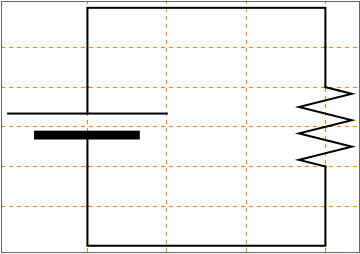
or placing the resistor vertically:
display[{battery[] // at[{0, 0}, Pi/2],
connect[{{0, 1}, {0, 2}, {3, 2}, {3, 1}}],
resistor[] // at[{3, 0}, Pi/2],
connect[{{3, 0}, {3, -1}, {0, -1}, {0, 0}}]}]
connect[pointList_] := {Line[pointList],
Map[Text[Style["", FontSize -> 18]] &, pointList[[{1, -1}]]]}
gap[l_: 1] := Line[l {{{0, 0}, {1/3, 0}}, {{2/3, 0}, {1, 0}}}]
resistor[l_: 1, n_: 3] := Line[Table[{i l/(4 n), 1/3 Sin[i Pi/2]}, {i, 0, 4 n}]
battery[l_: 1] := {gap[ l], {Rectangle[l {1/3, -(2/3)}, l {1/3 + 1/9, 2/3}], Line[l {{2/3, -1}, {2/3, 1}}]}}
contact[l_: 1] := {gap[l], Map[{EdgeForm[Directive[Thick, Black]], FaceForm[White], Disk[#, l/30]} &, l {{1/3, 0}, {2/3, 0}}]}
Options[display] = {Frame -> True, FrameTicks -> None, PlotRange -> All, GridLines -> Automatic, GridLinesStyle -> Directive[Orange, Dashed], AspectRatio -> Automatic};
display[d_, opts : OptionsPattern[]] := Graphics[Style[d, Thick], Join[FilterRules[{opts}, Options[Graphics]], Options[display]]]
at[position_, angle_: 0][obj_] := GeometricTransformation[obj, Composition[TranslationTransform[position], RotationTransform[angle]]]
label[s_String, color_: RGBColor[.3, .5, .8]] := Text@Style[s, FontColor -> color, FontFamily -> "Geneva", FontSize -> Large];
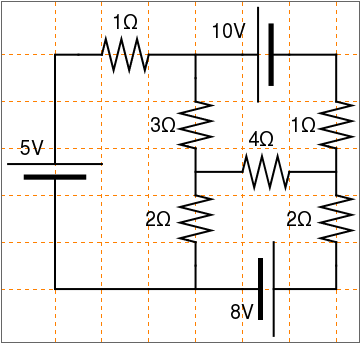
display[{battery[] // at[{0, -1}, Pi/2],
connect[{{0, 0}, {0, 2}, {1, 2}}], resistor[] // at[{1, 2}],
connect[{{2, 2}, {3, 2}, {3, 1}}], resistor[] // at[{3, 1}, 3 Pi/2],
connect[{{3, 0}, {3, -1}}], resistor[] // at[{3, -1}, 3 Pi/2], connect[{{2, -3}, {3, -3}, {3, -2}}],
connect[{{2, -3}, {0, -3}, {0, -1}}], connect[{{3, 2}, {4, 2}}],
battery[] // at[{5, 2}, Pi], connect[{{5, 2}, {6, 2}}],
battery[] // at[{4, -3}, 0], connect[{{3, -3}, {4, -3}}],
connect[{{5, -3}, {6, -3}, {6, -2}}],
resistor[] // at[{6, -1}, 3 Pi/2], connect[{{6, -1}, {6, 0}}],
resistor[] // at[{6, 1}, 3 Pi/2], connect[{{6, 2}, {6, 1}}],
connect[{{3, -0.5}, {4, -0.5}}], resistor[] // at[{4, -0.5}],
connect[{{5, -0.5}, {6, -0.5}}],
Text[Style["5V", FontSize -> 18], {-0.5, 0}],
Text[Style["10V", FontSize -> 18], {3.7, 2.5}],
Text[Style["8V", FontSize -> 18], {4, -3.5}],
Text[Style["1\[CapitalOmega]", FontSize -> 18], {1.5, 2.7}],
Text[Style["3\[CapitalOmega]", FontSize -> 18], {2.3, 0.5}],
Text[Style["1\[CapitalOmega]", FontSize -> 18], {5.3, 0.5}],
Text[Style["2\[CapitalOmega]", FontSize -> 18], {2.2, -1.5}],
Text[Style["4\[CapitalOmega]", FontSize -> 18], {4.4, 0.2}],
Text[Style["2\[CapitalOmega]", FontSize -> 18], {5.2, -1.5}]}]
or
gap[l_: 1] := Line[l {{{0, 0}, {1/3, 0}}, {{2/3, 0}, {1, 0}}}]
resistor[l_: 1, n_: 3] := Line[Table[{i l/(4 n), 1/3 Sin[i Pi/2]}, {i, 0, 4 n}]
battery[l_: 1] := {gap[ l], {Rectangle[l {1/3, -(2/3)}, l {1/3 + 1/9, 2/3}], Line[l {{2/3, -1}, {2/3, 1}}]}}
contact[l_: 1] := {gap[l], Map[{EdgeForm[Directive[Thick, Black]], FaceForm[White], Disk[#, l/30]} &, l {{1/3, 0}, {2/3, 0}}]}
Options[display] = {Frame -> True, FrameTicks -> None, PlotRange -> All, GridLines -> Automatic, GridLinesStyle -> Directive[Orange, Dashed], AspectRatio -> Automatic};
display[d_, opts : OptionsPattern[]] := Graphics[Style[d, Thick], Join[FilterRules[{opts}, Options[Graphics]], Options[display]]]
at[position_, angle_: 0][obj_] := GeometricTransformation[obj, Composition[TranslationTransform[position], RotationTransform[angle]]]
label[s_String, color_: RGBColor[.3, .5, .8]] := Text@Style[s, FontColor -> color, FontFamily -> "Geneva", FontSize -> Large];
display[{battery[] // at[{0, -1}, Pi/2],
connect[{{0, 0}, {0, 2}, {1, 2}}], resistor[] // at[{1, 2}],
connect[{{2, 2}, {3, 2}, {3, 1}}], resistor[] // at[{3, 1}, 3 Pi/2],
connect[{{3, 0}, {3, -1}}], resistor[] // at[{3, -1}, 3 Pi/2], connect[{{2, -3}, {3, -3}, {3, -2}}],
connect[{{2, -3}, {0, -3}, {0, -1}}], connect[{{3, 2}, {4, 2}}],
battery[] // at[{5, 2}, Pi], connect[{{5, 2}, {6, 2}}],
battery[] // at[{4, -3}, 0], connect[{{3, -3}, {4, -3}}],
connect[{{5, -3}, {6, -3}, {6, -2}}],
resistor[] // at[{6, -1}, 3 Pi/2], connect[{{6, -1}, {6, 0}}],
resistor[] // at[{6, 1}, 3 Pi/2], connect[{{6, 2}, {6, 1}}],
connect[{{3, -0.5}, {4, -0.5}}], resistor[] // at[{4, -0.5}],
connect[{{5, -0.5}, {6, -0.5}}],
Text[Style["5V", FontSize -> 18], {-0.5, 0}],
Text[Style["10V", FontSize -> 18], {3.7, 2.5}],
Text[Style["8V", FontSize -> 18], {4, -3.5}],
Text[Style["1\[CapitalOmega]", FontSize -> 18], {1.5, 2.7}],
Text[Style["3\[CapitalOmega]", FontSize -> 18], {2.3, 0.5}],
Text[Style["1\[CapitalOmega]", FontSize -> 18], {5.3, 0.5}],
Text[Style["2\[CapitalOmega]", FontSize -> 18], {2.2, -1.5}],
Text[Style["4\[CapitalOmega]", FontSize -> 18], {4.4, 0.2}],
Text[Style["2\[CapitalOmega]", FontSize -> 18], {5.2, -1.5}]}]
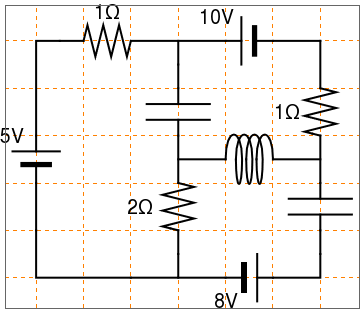
display[{battery[] // at[{0, -1}, Pi/2],
connect[{{0, 0}, {0, 2}, {1, 2}}], resistor[] // at[{1, 2}],
connect[{{2, 2}, {3, 2}, {3, 1}}],
capacitor[] // at[{3, 1}, 3 Pi/2], connect[{{3, 0}, {3, -1}}],
resistor[] // at[{3, -1}, 3 Pi/2],
connect[{{2, -3}, {3, -3}, {3, -2}}],
connect[{{2, -3}, {0, -3}, {0, -1}}], connect[{{3, 2}, {4, 2}}],
battery[] // at[{5, 2}, Pi], connect[{{5, 2}, {6, 2}}],
battery[] // at[{4, -3}, 0], connect[{{3, -3}, {4, -3}}],
connect[{{5, -3}, {6, -3}, {6, -2}}],
capacitor[] // at[{6, -1}, 3 Pi/2], connect[{{6, -1}, {6, 0}}],
resistor[] // at[{6, 1}, 3 Pi/2], connect[{{6, 2}, {6, 1}}],
connect[{{3, -0.5}, {4, -0.5}}], coil[] // at[{4, -0.5}],
connect[{{5, -0.5}, {6, -0.5}}],
Text[Style["5V", FontSize -> 18], {-0.5, 0}],
Text[Style["10V", FontSize -> 18], {3.8, 2.5}],
Text[Style["8V", FontSize -> 18], {4, -3.5}],
Text[Style["1\[CapitalOmega]", FontSize -> 18], {1.5, 2.6}],
Text[Style["1\[CapitalOmega]", FontSize -> 18], {5.3, 0.5}],
Text[Style["2\[CapitalOmega]", FontSize -> 18], {2.2, -1.5}]}]
l = Line[{{1, 0.2}, {1.8, 0.2}}];
l2 = Line[{{2, 0.2}, {2.8, 0.2}}];
l3 = Line[{{1, 1}, {2.8, 1}}];
l4 = Line[{{1, 1.8}, {1.8, 1.8}}];
l5 = Line[{{2, 1.8}, {2.8, 1.8}}];
l6 = Line[{{1, 2.6}, {1.8, 2.6}}];
l7 = Line[{{2, 2.6}, {2.8, 2.6}}];
l8 = Line[{{1.8, 0.1}, {1.8, 0.3}}];
l9 = Line[{{2, 0}, {2, 0.4}}];
l10 = Line[{{1.8, 1.7}, {1.8, 1.9}}];
l11 = Line[{{2, 1.6}, {2, 2}}];
l12 = Line[{{1.8, 2.5}, {1.8, 2.7}}];
l13 = Line[{{2, 2.4}, {2, 2.8}}];
h = Line[{{1, 0.2}, {1, 0.5}}];
h2 = Line[{{1, 0.7}, {1, 1}}];
h3 = Line[{{2.8, 0.2}, {2.8, 0.5}}];
h4 = Line[{{2.8, 0.7}, {2.8, 1}}];
h5 = Line[{{1, 1}, {1, 1.3}}];
h6 = Line[{{1, 1.5}, {1, 1.8}}];
h7 = Line[{{2.8, 1}, {2.8, 1.3}}];
h8 = Line[{{2.8, 1.5}, {2.8, 1.8}}];
h9 = Line[{{1, 1.8}, {1, 2.1}}];
h10 = Line[{{1, 2.3}, {1, 2.6}}];
h11 = Line[{{2.8, 1.8}, {2.8, 2.1}}];
h12 = Line[{{2.8, 2.3}, {2.8, 2.6}}];
saw = Line[{{1, 0.5}, {0.9, 0.55}, {1.1, 0.6}, {0.9, 0.65}, {1, 0.7}}];
saw2 = Line[{{2.8, 0.5}, {2.7, 0.55}, {2.9, 0.6}, {2.7, 0.65}, {2.8, 0.7}}];
saw3 = Line[{{1, 1.3}, {0.9, 1.35}, {1.1, 1.4}, {0.9, 1.45}, {1, 1.5}}];
saw4 = Line[{{2.8, 1.3}, {2.7, 1.35}, {2.9, 1.4}, {2.7, 1.45}, {2.8, 1.5}}];
saw5 = Line[{{1, 2.1}, {0.9, 2.15}, {1.1, 2.2}, {0.9, 2.25}, {1, 2.3}}];
saw6 = Line[{{2.8, 2.1}, {2.7, 2.15}, {2.9, 2.2}, {2.7, 2.25}, {2.8, 2.3}}];
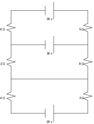
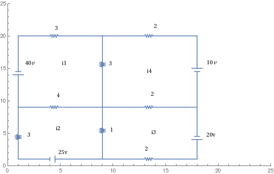
Graphics[{{l, Text[20 v, {1.9, 0}]}, {l2}, {l3}, {l4, Text[30 v, {1.9, 1.6}]}, {l5}, {l6}, {l7}, {l8, Text[30 v, {1.9, 2.4}]}, {l9}, {l10}, {l11}, {l12}, {l13}, {h}, {h2}, {h3}, {h4}, \ {h5}, {h6}, {h7}, {h8}, {h9}, {h10}, {h11}, {h12}, {saw, Text[4 \[CapitalOmega], {0.8, 0.56}]}, {saw2, Text[3 \[CapitalOmega], {2.65, 0.56}]}, {saw3, Text[2 \[CapitalOmega], {0.8, 1.36}]}, {saw4, Text[8 \[CapitalOmega], {2.65, 1.36}]}, {saw5, Text[6 \[CapitalOmega], {0.8, 2.16}]}, {saw6, Text[5 \[CapitalOmega], {2.65, 2.16}]}}]
l2 = Line[{{2, 0.2}, {2.8, 0.2}}];
l3 = Line[{{1, 1}, {2.8, 1}}];
l4 = Line[{{1, 1.8}, {1.8, 1.8}}];
l5 = Line[{{2, 1.8}, {2.8, 1.8}}];
l6 = Line[{{1, 2.6}, {1.8, 2.6}}];
l7 = Line[{{2, 2.6}, {2.8, 2.6}}];
l8 = Line[{{1.8, 0.1}, {1.8, 0.3}}];
l9 = Line[{{2, 0}, {2, 0.4}}];
l10 = Line[{{1.8, 1.7}, {1.8, 1.9}}];
l11 = Line[{{2, 1.6}, {2, 2}}];
l12 = Line[{{1.8, 2.5}, {1.8, 2.7}}];
l13 = Line[{{2, 2.4}, {2, 2.8}}];
h = Line[{{1, 0.2}, {1, 0.5}}];
h2 = Line[{{1, 0.7}, {1, 1}}];
h3 = Line[{{2.8, 0.2}, {2.8, 0.5}}];
h4 = Line[{{2.8, 0.7}, {2.8, 1}}];
h5 = Line[{{1, 1}, {1, 1.3}}];
h6 = Line[{{1, 1.5}, {1, 1.8}}];
h7 = Line[{{2.8, 1}, {2.8, 1.3}}];
h8 = Line[{{2.8, 1.5}, {2.8, 1.8}}];
h9 = Line[{{1, 1.8}, {1, 2.1}}];
h10 = Line[{{1, 2.3}, {1, 2.6}}];
h11 = Line[{{2.8, 1.8}, {2.8, 2.1}}];
h12 = Line[{{2.8, 2.3}, {2.8, 2.6}}];
saw = Line[{{1, 0.5}, {0.9, 0.55}, {1.1, 0.6}, {0.9, 0.65}, {1, 0.7}}];
saw2 = Line[{{2.8, 0.5}, {2.7, 0.55}, {2.9, 0.6}, {2.7, 0.65}, {2.8, 0.7}}];
saw3 = Line[{{1, 1.3}, {0.9, 1.35}, {1.1, 1.4}, {0.9, 1.45}, {1, 1.5}}];
saw4 = Line[{{2.8, 1.3}, {2.7, 1.35}, {2.9, 1.4}, {2.7, 1.45}, {2.8, 1.5}}];
saw5 = Line[{{1, 2.1}, {0.9, 2.15}, {1.1, 2.2}, {0.9, 2.25}, {1, 2.3}}];
saw6 = Line[{{2.8, 2.1}, {2.7, 2.15}, {2.9, 2.2}, {2.7, 2.25}, {2.8, 2.3}}];
Graphics[{{l, Text[20 v, {1.9, 0}]}, {l2}, {l3}, {l4, Text[30 v, {1.9, 1.6}]}, {l5}, {l6}, {l7}, {l8, Text[30 v, {1.9, 2.4}]}, {l9}, {l10}, {l11}, {l12}, {l13}, {h}, {h2}, {h3}, {h4}, \ {h5}, {h6}, {h7}, {h8}, {h9}, {h10}, {h11}, {h12}, {saw, Text[4 \[CapitalOmega], {0.8, 0.56}]}, {saw2, Text[3 \[CapitalOmega], {2.65, 0.56}]}, {saw3, Text[2 \[CapitalOmega], {0.8, 1.36}]}, {saw4, Text[8 \[CapitalOmega], {2.65, 1.36}]}, {saw5, Text[6 \[CapitalOmega], {0.8, 2.16}]}, {saw6, Text[5 \[CapitalOmega], {2.65, 2.16}]}}]
p1 = ListLinePlot[{{1, 1}, {4, 1}, \!\(\*
TagBox[
FrameBox["\[Ellipsis]"],
"Placeholder"]\)}, PlotRange -> {{0, 25}, {0, 25}}];
p2 = ListLinePlot[{{4, 0.75}, {4, 1.25}}, PlotRange -> {{0, 25}, {0, 25}}];
p3 = ListLinePlot[{{1, 1}, {1, 4}, \!\(\* TagBox[ FrameBox["\[Ellipsis]"], "Placeholder"]\)}, PlotRange -> {{0, 25}, {0, 25}}];
p4 = ListLinePlot[{{4.5, 0.5}, {4.5, 1.50}, \!\(\* TagBox[ FrameBox["\[Ellipsis]"], "Placeholder"]\)}, PlotRange -> {{0, 25}, {0, 25}}];
p5 = ListLinePlot[{{4.5, 1}, {13, 1}, \!\(\* TagBox[ FrameBox["\[Ellipsis]"], "Placeholder"]\)}, PlotRange -> {{0, 25}, {0, 25}}];
p6 = ListLinePlot[{{9, 1}, {9, 5}, \!\(\* TagBox[ FrameBox["\[Ellipsis]"], "Placeholder"]\)}, PlotRange -> {{0, 25}, {0, 25}}];
p7 = ListLinePlot[{{13.9, 1}, {18, 1}, {18, 1}, {18, 4}}, PlotRange -> {{0, 25}, {0, 25}}];
p8 = ListLinePlot[{{17.5, 4}, {18.5, 4}, \!\(\* TagBox[ FrameBox["\[Ellipsis]"], "Placeholder"]\)}, PlotRange -> {{0, 25}, {0, 25}}];
p9 = ListLinePlot[{{17.75, 4.5}, {18.25, 4.5}, \!\(\* TagBox[ FrameBox["\[Ellipsis]"], "Placeholder"]\)}, PlotRange -> {{0, 25}, {0, 25}}];
p10 = ListLinePlot[{{18, 4.5}, {18, 9}, \!\(\* TagBox[ FrameBox["\[Ellipsis]"], "Placeholder"]\)}, PlotRange -> {{0, 25}, {0, 25}}];
m1 = ListLinePlot[{{13, 1}, {13.1, 1.2}, {13.2, .8}, {13.3, 1.2}, {13.4, .8}, {13.5, 1.2}, {13.6, .8}, {13.7, 1.2}, {13.8, 1}}, PlotRange -> {{0, 25}, {0, 25}}];
m2 = ListLinePlot[{{9, 5}, {8.8, 5.1}, {9.2, 5.2}, {8.8, 5.3}, {9.2, 5.4}, {8.8, 5.5}, {9.2, 5.6}, {8.8, 5.7}, {9.0, 5.8}}, PlotRange -> {{0, 25}, {0, 25}}];
m3 = ListLinePlot[{{1, 4}, {.8, 4.1}, {1.2, 4.2}, {.8, 4.3}, {1.2, 4.4}, {.8, 4.5}, {1.2, 4.6}, {.8, 4.7}, {1.0, 4.8}}, PlotRange -> {{0, 25}, {0, 25}}];
p11 = ListLinePlot[{{1, 4.8}, {1, 9}}, PlotRange -> {{0, 25}, {0, 25}}];
p12 = ListLinePlot[{{1, 9}, {5, 9}, \!\(\* TagBox[ FrameBox["\[Ellipsis]"], "Placeholder"]\)}, PlotRange -> {{0, 25}, {0, 25}}];
m4 = ListLinePlot[{{4, 9}, {4.1, 9.2}, {4.2, 8.8}, {4.3, 9.2}, {4.4, 8.8}, {4.5, 9.2}, {4.6, 8.8}, {4.7, 9.2}, {4.8, 9}}, PlotRange -> {{0, 25}, {0, 25}}];
p12 = ListLinePlot[{{4.8, 9}, {9, 9}, \!\(\* TagBox[ FrameBox["\[Ellipsis]"], "Placeholder"]\)}, PlotRange -> {{0, 25}, {0, 25}}]; p13 = ListLinePlot[{{9, 9}, {9, 5.8}}, PlotRange -> {{0, 25}, {0, 25}}];
p14 = ListLinePlot[{{1, 9}, {4, 9}, \!\(\* TagBox[ FrameBox["\[Ellipsis]"], "Placeholder"]\)}, PlotRange -> {{0, 25}, {0, 25}}];
p15 = ListLinePlot[{{1, 9}, {1, 14}}, PlotRange -> {{0, 25}, {0, 25}}];
p16 = ListLinePlot[{{0.5, 14}, {1.5, 14}, \!\(\* TagBox[ FrameBox["\[Ellipsis]"], "Placeholder"]\)}, PlotRange -> {{0, 25}, {0, 25}}];
p17 = ListLinePlot[{{.75, 14.50}, {1.25, 14.50}, \!\(\* TagBox[ FrameBox["\[Ellipsis]"], "Placeholder"]\)}, PlotRange -> {{0, 25}, {0, 25}}];
p18 = ListLinePlot[{{1, 14.50}, {1, 20}, \!\(\* TagBox[ FrameBox["\[Ellipsis]"], "Placeholder"]\)}, PlotRange -> {{0, 25}, {0, 25}}];
p19 = ListLinePlot[{{1, 20}, {4, 20}, \!\(\* TagBox[ FrameBox["\[Ellipsis]"], "Placeholder"]\)}, PlotRange -> {{0, 25}, {0, 25}}];
m5 = ListLinePlot[{{4, 20}, {4.1, 20.2}, {4.2, 19.8}, {4.3, 20.2}, {4.4, 19.8}, {4.5, 20.2}, {4.6, 19.8}, {4.7, 20.2}, {4.8, 20}}, PlotRange -> {{0, 25}, {0, 25}}];
p20 = ListLinePlot[{{4.8, 20}, {9, 20}, \!\(\* TagBox[ FrameBox["\[Ellipsis]"], "Placeholder"]\)}, PlotRange -> {{0, 25}, {0, 25}}];
p21 = ListLinePlot[{{9, 20}, {9, 16}, \!\(\* TagBox[ FrameBox["\[Ellipsis]"], "Placeholder"]\)}, PlotRange -> {{0, 25}, {0, 25}}];
m6 = ListLinePlot[{{9, 16}, {8.8, 15.9}, {9.2, 15.8}, {8.8, 15.7}, {9.2, 15.6}, {8.8, 15.5}, {9.2, 15.4}, {8.8, 15.3}, {9.0, 15.2}}, PlotRange -> {{0, 25}, {0, 25}}];
p22 = ListLinePlot[{{9, 15.2}, {9, 9}, \!\(\* TagBox[ FrameBox["\[Ellipsis]"], "Placeholder"]\)}, PlotRange -> {{0, 25}, {0, 25}}];
p23 = ListLinePlot[{{9, 9}, {13, 9}, \!\(\* TagBox[ FrameBox["\[Ellipsis]"], "Placeholder"]\)}, PlotRange -> {{0, 25}, {0, 25}}];
m7 = ListLinePlot[{{13, 9}, {13.1, 9.2}, {13.2, 8.8}, {13.3, 9.2}, {13.4, 8.8}, {13.5, 9.2}, {13.6, 8.8}, {13.7, 9.2}, {13.8, 9}}, PlotRange -> {{0, 25}, {0, 25}}];
p24 = ListLinePlot[{{13.8, 9}, {18, 9}, \!\(\* TagBox[ FrameBox["\[Ellipsis]"], "Placeholder"]\)}, PlotRange -> {{0, 25}, {0, 25}}];
p25 = ListLinePlot[{{9, 20}, {13, 20}, \!\(\* TagBox[ FrameBox["\[Ellipsis]"], "Placeholder"]\)}, PlotRange -> {{0, 25}, {0, 25}}];
m8 = ListLinePlot[{{13, 20}, {13.1, 20.2}, {13.2, 19.8}, {13.3, 20.2}, {13.4, 19.8}, {13.5, 20.2}, {13.6, 19.8}, {13.7, 20.2}, {13.8, 20}}, PlotRange -> {{0, 25}, {0, 25}}];
p26 = ListLinePlot[{{13.8, 20}, {18, 20}, \!\(\* TagBox[ FrameBox["\[Ellipsis]"], "Placeholder"]\)}, PlotRange -> {{0, 25}, {0, 25}}];
p27 = ListLinePlot[{{18, 20}, {18, 15}, \!\(\* TagBox[ FrameBox["\[Ellipsis]"], "Placeholder"]\)}, PlotRange -> {{0, 25}, {0, 25}}];
p28 = ListLinePlot[{{17.5, 15}, {18.5, 15}, \!\(\* TagBox[ FrameBox["\[Ellipsis]"], "Placeholder"]\)}, PlotRange -> {{0, 25}, {0, 25}}];
p29 = ListLinePlot[{{17.75, 14.5}, {18.25, 14.5}, \!\(\* TagBox[ FrameBox["\[Ellipsis]"], "Placeholder"]\)}, PlotRange -> {{0, 25}, {0, 25}}];
p30 = ListLinePlot[{{18, 14.5}, {18, 9}, \!\(\* TagBox[ FrameBox["\[Ellipsis]"], "Placeholder"]\)}, PlotRange -> {{0, 25}, {0, 25}}];
Show[p1, p2, p3, p4, p5, p6, m1, p7, p8, p9, p10, m2, m3, p11, p12, \ m4, p13, p14, p15, p16, p17, p18, m5, p19, p20, p21, m6, p22, p23, \ m7, p24, m8, p25, p26, p27, p28, p29, p30]
connect[pointList_] := {Line[pointList],
Map[Text[Style["", FontSize -> 18]] &, pointList[[{1, -1}]]]};
gap[l_: 1] := Line[l {{{0, 0}, {1/3, 0}}, {{2/3, 0}, {1, 0}}}];
battery[l_: 1] := {gap[ l], {Rectangle[l {1/3, -(2/3)}, l {1/3 + 1/9, 2/3}], Line[l {{2/3, -1}, {2/3, 1}}]}};
resistor[l_: 1, n_: 3] := Line[Table[{i l/(4 n), 1/3 Sin[i Pi/2]}, {i, 0, 4 n}]];
contact[l_: 1] := {gap[l], Map[{EdgeForm[Directive[Thick, Black]], FaceForm[White], Disk[#, l/30]} &, l {{1/3, 0}, {2/3, 0}}]} Options[display] = {Frame -> True, FrameTicks -> None, PlotRange -> All, GridLines -> Automatic, GridLinesStyle -> Directive[Orange, Dashed], AspectRatio -> Automatic};
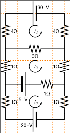
display[d_, opts : OptionsPattern[]] := Graphics[Style[d, Thick], Join[FilterRules[{opts}, Options[Graphics]], Options[display]]]; at[position_, angle_: 0][obj_] := GeometricTransformation[obj, Composition[TranslationTransform[position], RotationTransform[angle]]]; label[s_String, color_: RGBColor[.3, .5, .8]] := Text@Style[s, FontColor -> color, FontFamily -> "Times", FontSize -> Large]; display[{battery[] // at[{3, 4}, Pi], connect[{{0, 3}, {0, 4}, {2, 4}}], resistor[] // at[{0, 3}, 3 Pi/2], connect[{{0, 2}, {0, 0}}], resistor[] // at[{0, 0}, 3 Pi/2], connect[{{0, -1}, {0, -3}}], resistor[] // at[{0, -3}, 3 Pi/2], connect[{{0, -4}, {0, -5}, {2, -5}}], battery[] // at[{3, -5}, Pi], connect[{{3, -5}, {5, -5}, {5, -4}}], resistor[] // at[{5, -3}, 3 Pi/2], connect[{{5, -3}, {5, -1}}], resistor[] // at[{5, 0}, 3 Pi/2], connect[{{5, 0}, {5, 2}}], resistor[] // at[{5, 3}, 3 Pi/2], connect[{{5, 3}, {5, 4}, {3, 4}}], connect[{{0, 1}, {2, 1}}], resistor[] // at[{2, 1}], connect[{{3, 1}, {5, 1}}], connect[{{0, -2}, {1, -2}}], battery[] // at[{1, -2}], connect[{{2, -2}, {3, -2}}], resistor[] // at[{3, -2}], connect[{{4, -2}, {5, -2}}], Circle[{2.5, 2.5}, 0.5, {Pi/3, 7 Pi/4}], Arrow[{{2.87, 2.12}, {3.1, 2.5}}], Text[Style["I", FontSize -> 15, FontFamily -> "Times New Roman", FontSlant -> Italic], {2.5, 2.5}], Text[Style["1", FontSize -> 10, FontFamily -> "Times New Roman", FontSlant -> Italic], {2.65, 2.4}], Circle[{2.5, -0.5}, 0.5, {Pi/3, 7 Pi/4}], Arrow[{{2.87, -0.88}, {3.1, -0.5}}], Text[Style["I", FontSize -> 15, FontFamily -> "Times New Roman", FontSlant -> Italic], {2.5, -0.5}], Text[Style["2", FontSize -> 10, FontFamily -> "Times New Roman", FontSlant -> Italic], {2.65, -0.6}], Circle[{2.5, -3.5}, 0.5, {Pi/3, 7 Pi/4}], Arrow[{{2.87, -3.88}, {3.1, -3.5}}], Text[Style["I", FontSize -> 15, FontFamily -> "Times New Roman", FontSlant -> Italic], {2.5, -3.5}], Text[Style["3", FontSize -> 10, FontFamily -> "Times New Roman", FontSlant -> Italic], {2.65, -3.6}], Text[Style["30-V", FontSize -> 15], {3.2, 4.5}], Text[Style["4\[CapitalOmega]", FontSize -> 15], {4.3, 2.5}], Text[Style["1\[CapitalOmega]", FontSize -> 15], {4.3, -0.5}], Text[Style["1\[CapitalOmega]", FontSize -> 15], {4.3, -3.5}], Text[Style["4\[CapitalOmega]", FontSize -> 15], {0.7, 2.5}], Text[Style["1\[CapitalOmega]", FontSize -> 15], {0.7, -0.5}], Text[Style["1\[CapitalOmega]", FontSize -> 15], {0.7, -3.5}], Text[Style["5-V", FontSize -> 15], {1.5, -3.3}], Text[Style["1\[CapitalOmega]", FontSize -> 15], {3.5, -2.8}], Text[Style["3\[CapitalOmega]", FontSize -> 15], {2.5, 0.4}], Text[Style["20-V", FontSize -> 15], {1.8, -5.5}]}]
gap[l_: 1] := Line[l {{{0, 0}, {1/3, 0}}, {{2/3, 0}, {1, 0}}}];
battery[l_: 1] := {gap[ l], {Rectangle[l {1/3, -(2/3)}, l {1/3 + 1/9, 2/3}], Line[l {{2/3, -1}, {2/3, 1}}]}};
resistor[l_: 1, n_: 3] := Line[Table[{i l/(4 n), 1/3 Sin[i Pi/2]}, {i, 0, 4 n}]];
contact[l_: 1] := {gap[l], Map[{EdgeForm[Directive[Thick, Black]], FaceForm[White], Disk[#, l/30]} &, l {{1/3, 0}, {2/3, 0}}]} Options[display] = {Frame -> True, FrameTicks -> None, PlotRange -> All, GridLines -> Automatic, GridLinesStyle -> Directive[Orange, Dashed], AspectRatio -> Automatic};
display[d_, opts : OptionsPattern[]] := Graphics[Style[d, Thick], Join[FilterRules[{opts}, Options[Graphics]], Options[display]]]; at[position_, angle_: 0][obj_] := GeometricTransformation[obj, Composition[TranslationTransform[position], RotationTransform[angle]]]; label[s_String, color_: RGBColor[.3, .5, .8]] := Text@Style[s, FontColor -> color, FontFamily -> "Times", FontSize -> Large]; display[{battery[] // at[{3, 4}, Pi], connect[{{0, 3}, {0, 4}, {2, 4}}], resistor[] // at[{0, 3}, 3 Pi/2], connect[{{0, 2}, {0, 0}}], resistor[] // at[{0, 0}, 3 Pi/2], connect[{{0, -1}, {0, -3}}], resistor[] // at[{0, -3}, 3 Pi/2], connect[{{0, -4}, {0, -5}, {2, -5}}], battery[] // at[{3, -5}, Pi], connect[{{3, -5}, {5, -5}, {5, -4}}], resistor[] // at[{5, -3}, 3 Pi/2], connect[{{5, -3}, {5, -1}}], resistor[] // at[{5, 0}, 3 Pi/2], connect[{{5, 0}, {5, 2}}], resistor[] // at[{5, 3}, 3 Pi/2], connect[{{5, 3}, {5, 4}, {3, 4}}], connect[{{0, 1}, {2, 1}}], resistor[] // at[{2, 1}], connect[{{3, 1}, {5, 1}}], connect[{{0, -2}, {1, -2}}], battery[] // at[{1, -2}], connect[{{2, -2}, {3, -2}}], resistor[] // at[{3, -2}], connect[{{4, -2}, {5, -2}}], Circle[{2.5, 2.5}, 0.5, {Pi/3, 7 Pi/4}], Arrow[{{2.87, 2.12}, {3.1, 2.5}}], Text[Style["I", FontSize -> 15, FontFamily -> "Times New Roman", FontSlant -> Italic], {2.5, 2.5}], Text[Style["1", FontSize -> 10, FontFamily -> "Times New Roman", FontSlant -> Italic], {2.65, 2.4}], Circle[{2.5, -0.5}, 0.5, {Pi/3, 7 Pi/4}], Arrow[{{2.87, -0.88}, {3.1, -0.5}}], Text[Style["I", FontSize -> 15, FontFamily -> "Times New Roman", FontSlant -> Italic], {2.5, -0.5}], Text[Style["2", FontSize -> 10, FontFamily -> "Times New Roman", FontSlant -> Italic], {2.65, -0.6}], Circle[{2.5, -3.5}, 0.5, {Pi/3, 7 Pi/4}], Arrow[{{2.87, -3.88}, {3.1, -3.5}}], Text[Style["I", FontSize -> 15, FontFamily -> "Times New Roman", FontSlant -> Italic], {2.5, -3.5}], Text[Style["3", FontSize -> 10, FontFamily -> "Times New Roman", FontSlant -> Italic], {2.65, -3.6}], Text[Style["30-V", FontSize -> 15], {3.2, 4.5}], Text[Style["4\[CapitalOmega]", FontSize -> 15], {4.3, 2.5}], Text[Style["1\[CapitalOmega]", FontSize -> 15], {4.3, -0.5}], Text[Style["1\[CapitalOmega]", FontSize -> 15], {4.3, -3.5}], Text[Style["4\[CapitalOmega]", FontSize -> 15], {0.7, 2.5}], Text[Style["1\[CapitalOmega]", FontSize -> 15], {0.7, -0.5}], Text[Style["1\[CapitalOmega]", FontSize -> 15], {0.7, -3.5}], Text[Style["5-V", FontSize -> 15], {1.5, -3.3}], Text[Style["1\[CapitalOmega]", FontSize -> 15], {3.5, -2.8}], Text[Style["3\[CapitalOmega]", FontSize -> 15], {2.5, 0.4}], Text[Style["20-V", FontSize -> 15], {1.8, -5.5}]}]
label[s_String, color_: RGBColor[.3, .5, .8]] :=
Text@Style[s, FontColor -> color, FontFamily -> "Times",
FontSize -> Large];
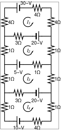
display[{battery[] // at[{2, 4}, Pi],
connect[{{0, 3}, {0, 4}, {1, 4}}], resistor[] // at[{0, 3}, 3 Pi/2],
connect[{{0, 2}, {0, 0}}], resistor[] // at[{0, 0}, 3 Pi/2],
connect[{{0, -1}, {0, -3}}], resistor[] // at[{0, -3}, 3 Pi/2],
connect[{{0, -4}, {0, -5}, {1, -5}}], resistor[] // at[{1, -5}],
connect[{{2, -5}, {3, -5}}], battery[] // at[{3, -5}],
connect[{{4, -5}, {5, -5}, {5, -4}}],
resistor[] // at[{5, -3}, 3 Pi/2], connect[{{5, -3}, {5, -1}}],
resistor[] // at[{5, 0}, 3 Pi/2], connect[{{5, 0}, {5, 2}}],
resistor[] // at[{5, 3}, 3 Pi/2], connect[{{5, 3}, {5, 4}, {4, 4}}],
resistor[] // at[{3, 4}], connect[{{2, 4}, {3, 4}}],
connect[{{0, 1}, {1, 1}}], resistor[] // at[{1, 1}],
connect[{{2, 1}, {3, 1}}], battery[] // at[{3, 1}],
connect[{{4, 1}, {5, 1}}], connect[{{0, -2}, {1, -2}}],
battery[] // at[{2, -2}, Pi], connect[{{2, -2}, {3, -2}}],
resistor[] // at[{3, -2}], connect[{{4, -2}, {5, -2}}],
connect[{{0, -5}, {0, -6}}], resistor[] // at[{0, -6}, 3 Pi/2],
connect[{{0, -7}, {0, -8}, {1, -8}}], battery[] // at[{2, -8}, Pi],
connect[{{2, -8}, {3, -8}}], resistor[] // at[{3, -8}],
connect[{{4, -8}, {5, -8}, {5, -7}}],
resistor[] // at[{5, -6}, 3 Pi/2], connect[{{5, -6}, {5, -5}}],
Circle[{2.5, 2.5}, 0.5, {Pi/3, 7 Pi/4}],
Arrow[{{2.82, 2.12}, {3.1, 2.5}}],
Text[Style["I", FontSize -> 15, FontFamily -> "Times New Roman",
FontSlant -> Italic], {2.5, 2.5}],
Text[Style["1", FontSize -> 10, FontFamily -> "Times New Roman",
FontSlant -> Italic], {2.65, 2.4}],
Circle[{2.5, -0.5}, 0.5, {Pi/3, 7 Pi/4}],
Arrow[{{2.82, -0.88}, {3.1, -0.5}}],
Text[Style["I", FontSize -> 15, FontFamily -> "Times New Roman",
FontSlant -> Italic], {2.5, -0.5}],
Text[Style["2", FontSize -> 10, FontFamily -> "Times New Roman",
FontSlant -> Italic], {2.65, -0.6}],
Circle[{2.5, -3.5}, 0.5, {Pi/3, 7 Pi/4}],
Arrow[{{2.82, -3.88}, {3.1, -3.5}}],
Text[Style["I", FontSize -> 15, FontFamily -> "Times New Roman",
FontSlant -> Italic], {2.5, -3.5}],
Text[Style["3", FontSize -> 10, FontFamily -> "Times New Roman",
FontSlant -> Italic], {2.65, -3.6}],
Circle[{2.5, -6.5}, 0.5, {Pi/3, 7 Pi/4}],
Arrow[{{2.82, -6.88}, {3.1, -6.5}}],
Text[Style["I", FontSize -> 15, FontFamily -> "Times New Roman",
FontSlant -> Italic], {2.5, -6.5}],
Text[Style["4", FontSize -> 10, FontFamily -> "Times New Roman",
FontSlant -> Italic], {2.65, -6.6}],
Text[Style["30-V", FontSize -> 15], {2.3, 4.5}],
Text[Style["4\[CapitalOmega]", FontSize -> 15], {5.7, 2.5}],
Text[Style["1\[CapitalOmega]", FontSize -> 15], {5.7, -0.5}],
Text[Style["1\[CapitalOmega]", FontSize -> 15], {5.7, -3.5}],
Text[Style["1\[CapitalOmega]", FontSize -> 15], {5.7, -6.5}],
Text[Style["4\[CapitalOmega]", FontSize -> 15], {0.7, 2.5}],
Text[Style["1\[CapitalOmega]", FontSize -> 15], {0.7, -0.5}],
Text[Style["1\[CapitalOmega]", FontSize -> 15], {0.7, -3.5}],
Text[Style["1\[CapitalOmega]", FontSize -> 15], {0.7, -6.5}],
Text[Style["5-V", FontSize -> 15], {1.5, -2.8}],
Text[Style["1\[CapitalOmega]", FontSize -> 15], {3.5, -2.8}],
Text[Style["3\[CapitalOmega]", FontSize -> 15], {1.5, 0.3}],
Text[Style["20-V", FontSize -> 15], {3.5, -5.8}],
Text[Style["4\[CapitalOmega]", FontSize -> 15], {3.5, 3.3}],
Text[Style["20-V", FontSize -> 15], {3.5, 0.3}],
Text[Style["3\[CapitalOmega]", FontSize -> 15], {1.5, -5.8}],
Text[Style["10-V", FontSize -> 15], {1.5, -8.7}],
Text[Style["4\[CapitalOmega]", FontSize -> 15], {3.5, -8.7}]}]